1080p Full HD 802.11n Wireless Interactive Presentation Gateway

PLANET WIPG-300H adopting IEEE 802.11n dual-band wireless technology brings smooth display through the 300Mbps high-speed wireless connection or the wired 100Mbps Fast Ethernet connection to project the screen of desktop PC, Mac or smartphone to make the professional and interactive presentation.

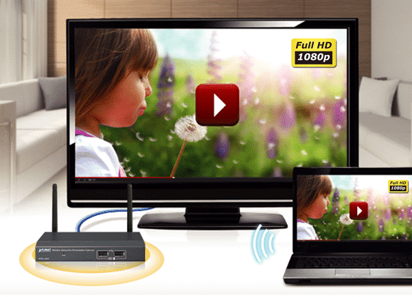
Intelligent 1080p Full HD Wireless Projection

The WIPG-300H can optimize resolution based on the automatically transmitting device. It supports the display with multiple resolutions and audio projection disregarding video format and resolution. Its HDMI output resolution can be increased to 1080p (1920 x 1080 pixels), making it a high-definition display perfect for presentation and video. Thus, the office presenter or the home users can easily share the multimedia on the big monitor/screen with others without the hassle of cabling.

Key Features:

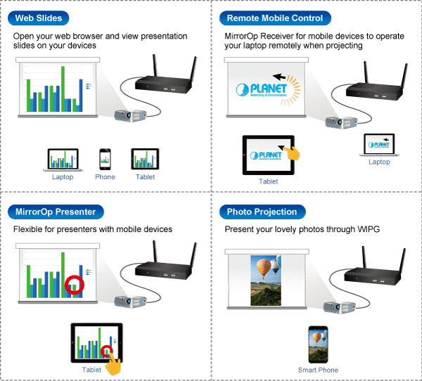
  •     Wirelessly project multimedia across different platforms
  •     Flexible dual-output options with VGA or 1080p Full HD resolution
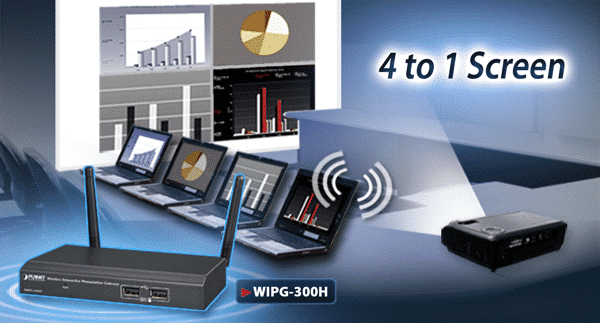
  •     4-to-1 split screen projection increase efficiency
  •     Audio and video streaming
  •     Just Plug & Display by a USB token without any installation
  •     802.11n dual-band Wi-Fi AP and AP-client mode
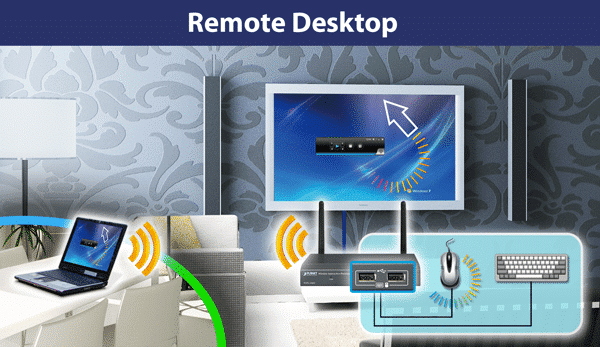
  •     Remote control presenter’s desktop over USB mouse/keyboard
  •     USB over IP for touch screen and IWB
  •     Web-based management interface
  •     Windows 7/8/10, Mac OS X, iOS and Android support
  •     WebSlides allows multiple users to view the presentation on any mobile devices
  •     SidePad receiver allows a mobile device to remotely control presenter’s desktop
  •     Its compact size makes installation and placement convenient

Wireless Interactive Touch

Furthermore, the WIPG-300H adopts an interactive feature with IWB (Intelligent White Board) and Mobile apps which enable users to reverse control or synchronize screen display for different platforms. This helps the WIPG-300H achieve a real, full wireless presentation environment.

Mobile Applications

The WIPG-300H supports not only the Windows and Mac platforms, but also the presentation and screen mirroring through the iPad, iPhone, or the Android mobile device. Apps for mobile devices working on the WIPG-300H are freely available at Google Play and Apple App Store.

Flexible Projection via Dual Video Output Interfaces

To deliver a perfect presentation solution, the WIPG-300H offers the choice of the two types of video output interfaces: the VGA or HDMI connector, which is compatible with most of the popular display devices. With the hardware decoding capability, the WIPG-300H can project high-definition sound film through wireless or wired LAN connections. It facilitates multiple users to freely display the presentations, images and videos via connecting to a projector or LCD TV without complex installation.

Remote Desktop

Plug standard USB keyboard or mouse into the USB port on the front panel of the WIPG-300H to enable you to control your PC remotely. You don’t have to stand still beside the PC or the WIPG-300H, thus delivering your presentation easily and freely.

4-to-1 Split Screen Projection

With this 4-to-1 split screen feature, the WIPG-300H allows up to four PC / Laptop screens to be projected through one projector at the same time. Therefore, the participants can easily do the side-by-side comparison from four PCs/laptops to make the presentation more efficient.

Cost Effective Industrial Wifi

Now available in stock – JAYCOR offers a complete end-to-end solution for cost-effective industrial/outdoor ruggedized Wifi. Purchase all components for a turnkey solution:

  • Wireless AP (Access Point)
  • Omni or directional antennas
  • Antenna (N-Type) & Ethernet (RJ45) patch cords
  • Antenna & Ethernet lighting surge protection
  • Din Rail /Wall Mount PoE Switches, Media Converters and SFP modules
  • Din Rail Power Supplies & cabtyre
  • Outdoor enclosure


Common Questions: HDBaseT

HDBaseT has become the leading solution for delivering ultra-high-definition (UHD) 4K video and audio, USB 2.0, 100 MB Ethernet, control and 100W on a single cable. This is what the HDBaseT Alliance refers to as the “5Play™ feature set.” It’s a huge benefit to have one cable that supports all these applications up to 330 ft for AV installations.

How HDBaseT Works with HDMI

The HDMI connector has become the industry standard for AV applications. It’s estimated that there are more than 4 billion HDMI devices currently in use. The HDMI 1.4 specification requires bandwidth of almost 10 Gbps. The HDMI 2.0 specification requires 18 Gbps, and the new HDMI 2.1 specification requires 48 Gbps. It’s clear that we’re seeing a rapid increase in bandwidth demand.

HDMI cables, however, have some distance limitations. Anything longer than 15 ft should have a chip to boost the signal (directional). Anything longer than 50 ft should be over active optical connection (AOC). Note: Cable distances supported for the newest 2.1 specification are still unclear because products are not available yet. In addition to distance limitations, HDMI can be difficult to install because the cables aren’t typically field terminated. These limitations cause real problems, especially in commercial installations.

This is where HDBaseT steps in. It can take the HDMI input, along with the other 5Play technology signals, and transport it 330 ft over a field-terminable, 4-pair twisted copper cable. Not only can you achieve longer distances, but, with the use of a switch, you can use multiple inputs and outputs.

Although HDBaseT was originally intended to work with standard category cabling, there have been some issues. As a result, we recommend that you choose a cable designed for the HDBaseT system you’re implementing.

The Best Cabling System for HDBaseT

Belden has performed several cabling tests to analyze bundling, power and 4K performance among different cabling systems. These tests have identified the cabling that can reliably support HDBaseT technology.

During testing, key parameters were identified in HDBaseT signal and design. This resulted in Belden’s creation of the industry’s first cable designed specifically for HDBaseT 4K video. These key electrical parameters are increased over standard category cable while still maintaining a cable that’s easy to install due to size and flexibility.

Read full article

How PatchPro® Works

The key point is the Database

  • The Database sends all information / changes to the raphical user interface (GUI) through CADVANCE and or AutoCAD
  • The advantage of PatchPro is that you can manipulate the database by using the GUI which is quicker and easier
  • The Database and the GUI are connected. Objects changed on the system update in real-time

Key attributes of PatchPro® Software Solutions

Comprehensive technical functionality – both in the Facilities as well as in Data Centres.

  • Graphical User Interface’s (GUI) display:
  • Entire Facility & Multiple Site
  • Data Centre/s
  • Rack View/s
  • Open System (API) and database architecture

Empower your Data Centre Collocation Customers with PatchPro® Web

Real-time Online Access to Hosted Infrastructure

PatchPro® Web application provides a collocation data centre’s clients access to their hosted infrastructure, online through a user-friendly web interface. An amazing tool for empowering DC customers to access and view their network infrastructure, servers and other devices. View free ports and rack units, create patch or cross-connects between devices and send workorders direct to the NOC.

The results:

  • Provide Visibility
  • Improve Efficiency
  • Empower Customers

Web Features

Front (and back) and rear (and back) views provide full visibility of all hosted infrastructure within the rack.

– user level access restricts collocations customers from accessing and viewing other customers infrastructure.

Side rack view provides visibility in ensuring no conflicting space requirements apply, when adding additional hardware components.

Visualize connections in granular detail:

– Connected/open ports (front and back) visually

– All connected devices

– Export to Excel/Visio

Customers manage their infrastructure and connectivity

– Components (Servers, switches, SFP’s)

– Create Connections (Patches & Cross-Connects)

Access unique attributes for all connected devices


Additional Benefits of PatchPro® SaaS

  • SaaS (Software as a service)
    • No capital investment in licensing, hardware, staff and training required to execute
    • Contract based on your scope of work and customized for your requirements and budget
  • Open API

Other Modules (Included)

  • PactchPro® F – Facilities Manager
    • Infrastructure physical Layer management (iPLM)
  • PatchPro®I – Infrastructure Connection Manager
    • Data Centre Infrastructure management (DCIM)
    • Automated Infrastructure Management (AIM)
  • PatchPro® SPM Web
    • Service Plan Manager/Asset Managment


Greg Pokroy

CEO – JAYCOR International

Enhance Performance, Productivity and Well-being with Human-Centric PoE LED Lighting

Power over Ethernet (PoE) makes it easier and more cost efficient to power all the “things” that make up Internet of Things and smart buildings. Why? Because, with PoE, powering these devices doesn’t require a power connection and a data connection. Through a single category cable, both power and data can be delivered to a device.

Prior to PoE, these systems may have been able to come together over one IP network for improved control and monitoring, but they still required separate data and electrical connections, as well as proximity to electrical outlets.

Over the past few years, PoE power levels have been increasing – starting at 15W and growing to 30W and 60W. Today, itp’s possible to deliver 100W of power plus data over a single cable. PoE standards are also changing to support higher power levels. IEEE 802.3bt, which is currently under development, calls for 4-pair power delivery to improve efficiency and support complex devices. It also calls for two power variants: Type 3 (60W) and Type 4 (100W).

These higher wattages allow devices like point-of-sale registers, digital signage displays and PTZ surveillance cameras to take advantage of PoE. LED lighting systems can also now connect to the network via a PoE cable.

Connecting LED lighting systems to the network via PoE offers many benefits. Each fixture can utilize a standard RJ45 connector and have its own IP address for individual monitoring and control. Through integrated sensors, LED fixtures transform into smart lighting systems that collect data on occupancy, temperature, daylight, etc. and make changes in lighting levels accordingly.

Who Benefits from PoE LED Lighting?

Although any facility can be a candidate for PoE LED lighting, healthcare facilities are noticing major improvements due to the impact it has on staff productivity and patient care and recovery.

PoE LED lighting offers a human-centric approach to lighting, recognizing that lighting can positively or negatively impact people. Lighting conditions can either disrupt or sync our circadian rhythms, which are physical, mental and behavioral changes that follow a 24-hour cycle. A human-centric approach to lighting means that it can be controlled to enhance performance, productivity and well-being.

In healthcare facilities, for example, fluorescent fixtures can be replaced with PoE LED fixtures that can be dimmed, color tuned and set to specific schedules. This not only improves sleep patterns for patients, decreases falls and reduces disruptive behavior (such as agitation or anger), but also lowers energy costs.

Installation and Deployment Challenges

There are certain challenges to keep in mind when deploying PoE LED lighting. For example, selecting the right option to power your LED lighting through the Ethernet network – either through centralized PoE, distributed/in-ceiling switches or a gateway – is crucial to ensuring that the system functions as expected and offers all promised benefits.

Read full article

JAYCOR – CEO announcement

JAYCOR International (Pty) Ltd is pleased to announce the appointment of Greg Pokroy, age 37, as the Company’s new CEO.

Greg joined JAYCOR in 2002 and began his career in sales, learning the products and business from the ground up. Greg moved to Cape Town in 2005 to begin developing client relationships in the Western and Eastern Cape regions, and later established JAYCOR’s Cape Town branch in 2010.

Over the last decade, Greg has played a strategic role in the growth, development and modernisation of the business, responsible for refining JAYCOR’s technology infrastructure, systems, operational processes and business development. Greg was also pivotal in successfully rebranding the business, launching the innovative smart e-commerce platform and spear-heading the Enterprise division and PatchPro® SaaS service.

The Board is excited to have Greg as CEO and we wish him great success in his new role.

Dual-Power Feeds in Data Centers

Things like always-on technology, streaming content and cloud adoption are creating high demand for efficient, resilient and fast data centers that never let us down.

To meet these needs, dual-power feeds – two independent electrical feeds coming into a data center from the utility company – are becoming more common to reduce the chance of a complete outage (or not having enough power). This type of power set-up is often seen in Tier 4 data centers. If one of the two power sources suffers from an interruption, the other source will still supply power.

Generally labeled “A” and “B” feeds, each power source has not only its own utility feed, but also:

  • A backup generator
  • A switch that alternates between A and B feeds
  • Electrical and distribution switchboards
  • An uninterruptible power supply (UPS)
  • A power distribution unit (PDU)
  • Rack-level PDUs

At any one of these points along the chain, failure can occur. A true dual-power feed means that there are two separate sets of these components operating independently, reducing the likelihood of downtime due to failure.

Today, most mission-critical IT equipment, such as servers and switches, are also designed with at least dual power supplies. When everything is running normally, the equipment pulls power equally from both power feeds. In the event of an outage, however, the IT equipment can automatically switch all power to one feed or the other.

Read full article

Network Upgrades: Utilizing Parallel Fiber Cabling

It comes to no surprise, that enterprise and consumer demands are impacting data centers and networks. As speed requirements go up, layer 0 (the physical media for data transmission) becomes increasingly critical to ensure link quality.

Numerous organizations are looking for an economical, futureproof migration path toward 100G (and beyond). Multimode fiber (MMF) cabling systems continue to be the most popular, futureproof cabling and connectivity solution.

Both duplex and parallel cabling are options for network upgrades. A few weeks ago, we discussed duplex MMF cabling. In this, we’ll discuss parallel MMF cabling.


Parallel Fiber Cabling

When transceiver technology can’t keep up with Ethernet speed requirements, the most obvious solution is to move from duplex to parallel fiber cabling.

Although using BiDi (bi-directional) and SWDM (shortwave wavelength division multiplexing) transceivers can reduce direct point-to-point cabling costs, they do not support breakout configuration (e.g. 40G switch ports to four 10G server ports), which is a very common use in data centers.

According to research firm LightCounting, approximately 50% of 40GBASE-SR4 QSFP+ form factors are deployed for breakout configuration; the other 50% are deployed for direct switch-to-switch links.

As a matter of fact, 40G QSFP+ and 100G QSFP28 are the most popular form factors used for Ethernet switches in data centers. QSFP (quad small form-factor) is a bi-directional, hot-pluggable module mainly designed for datacom applications. QSFP+/QSFP28 has a 2.5x data density compared to SFP+/SFP28, using four parallel electrical lanes. The optical interface is a receptacle for MPO female connectors. Four fibers (1, 2, 3 and 4) transmit the signal; the other four fibers (9, 10, 11 and 12) receive the optical signal.

QSFP transceivers, paired with parallel fiber connectivity with a one-row MPO-12 (Base-8 or Base-12) interface, can support flexible breakout or direct connection.

  • 40G/100G direct links are typically used in switch-to-switch links, which can be supported by duplex or parallel fiber cabling.
  • 40G/100G Ethernet ports can be configured as 4x 10G or 4x 25G ports to support 10G/25G server uplinks.
  • 40G/100GBASE-SR4 transceivers only use eight fiber threads in an MPO-12 connector; therefore, Base-8 is a cost-optimized cabling solution that allows 100% fiber utilization.

Read full article

Analyzing Data Center Energy Consumption By Using Business Metrics

About five years ago, the industry first heard about Digital Service Efficiency (DSE) – a method that was designed by eBay to help the company capture a holistic picture of their data center energy consumption and performance.

The initiative was then made public in an effort to assist other organizations establish their own data center energy consumption benchmarks and goals, and compare live system performance against those benchmarks and goals to determine actual efficiency levels.

While they tracking their data center’s power usage effectiveness (PUE), which illustrates how efficient a data center’s electrical and mechanical systems are, they felt like something was missing. Calculating PUE didn’t offer them insight into how efficiently their data center equipment (such as servers) was being used. The DSE initiative was formed to fill this gap.

Earlier this year, the team of eBay engineers who created the DSE initiative received a patent for it. With this news, we thought it would be a good time to revisit the data center productivity metric they introduced a few years ago. Even though it was created based on eBay’s core competency – e-commerce – there are still some lessons to be learned.

In eBay’s case, to measure performance and data center energy consumption, they chose to specifically measure how many online business transactions are completed per kilowatt-hour consumed. They calculated this by analyzing four metrics:

  1. The type of performance they wanted to measure (transactions, or the number of online purchases and sales)
  2. Cost per transaction (they measured cost per megawatt-hour, per user and per server)
  3. Environmental impact (amount of carbon dioxide produced per transaction)
  4. Revenue per transaction (they measured revenue per transaction, per megawatt-hour and per user)

Then they base their data center improvement goals around those metrics – goals like reducing cost per transaction by a certain percentage, for example, or increasing transactions per kilowatt-hour by a certain percentage.

The organization believes that, by substituting your own unique business metric in place of the metric they used – online business transactions – you’ll be able to create your own, unique way of measuring data center productivity and efficiency, too.

What performance metric could you use to measure and benchmark data center energy consumption? Here are a few ideas:

  • Healthcare: number of patients seen or number of appointments set
  • Hospitality: number of guests who stay onsite or number of reservations
  • Manufacturing: number of widgets produced
  • Financial: number of transactions

Read full article

Copyright © 2024 Jaycor International
Engineered by: NJIN Agency