Network Cables; How Cable Temperature Impacts Cable Reach

There is nothing more disheartening than making a big investment in something that promises to deliver what you require – only to find out once it is too late that it is not performing according to expectations. What happened? Is the product not adequate? Or is it not being utilised correctly?

Cable Performance Expectations

This scenario holds true with category cable investments as well. A cable that can not fulfil its 100 m channel reach (even though it is marketed as a 100 m cable) can derail network projects, increase costs, cause unplanned downtime and call for lots of troubleshooting (especially if the problem is not obvious right away).

High cable temperatures are sometimes to blame for cables that don’t perform up to the promised 100 m. Cables are rated to transmit data over a certain distance up to a certain temperature. When the cable heats up beyond that point, resistance and insertion loss increase; as a result, the channel reach of the cable often needs to be de-rated in order to perform as needed to transmit data.

Many factors cause cable temperatures to rise:

  • Cables installed above operational network equipment
  • Power being transmitted through bundled cabling
  • Uncontrolled ambient temperatures
  • Using the wrong category cabling for the job
  • Routing of cables near sources of heat

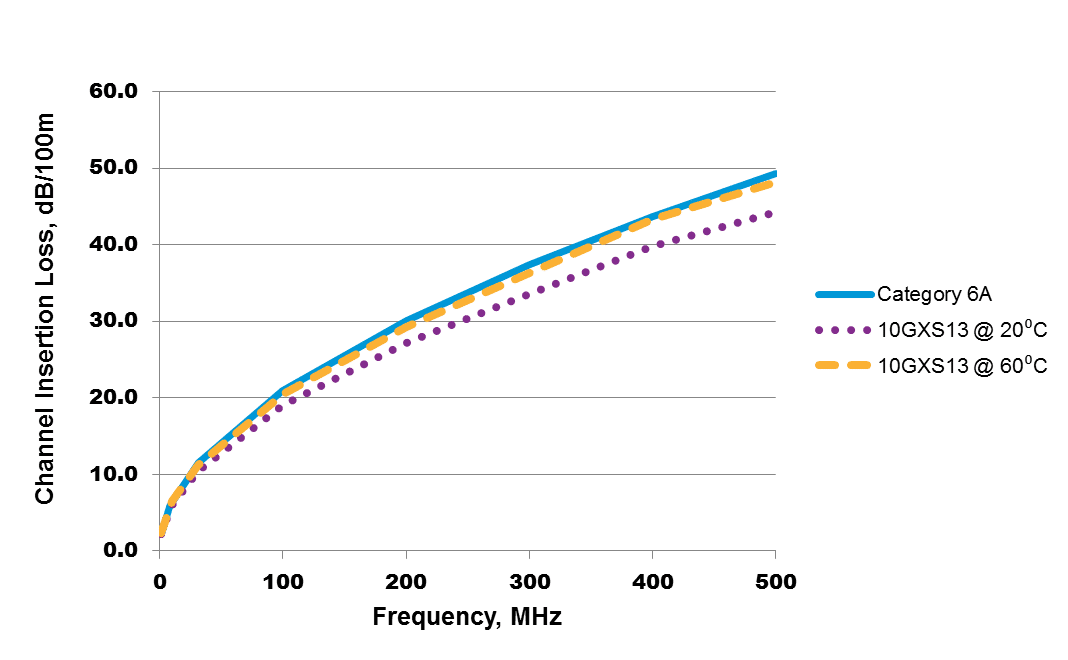
In Power over Ethernet (PoE) cables – which are becoming increasingly popular to support digital buildings and IoT – as power levels increase, so does the current level running through the cable. The amount of heat generated within the cable increases as well. Bundling makes temperatures rise even more; the heat generated by the current passing through the inner cables can’t escape. As temperatures rise, so does cable insertion loss, as pictured below.

Testing the Impacts of Cable Temperature on Reach

To assess this theory, I created a model to test temperature characteristics of different cables. Each cable was placed in an environmental chamber to measure insertion loss with cable temperature change. Data was generated for each cable; changes in insertion loss were recorded as the temperature changed.

The information gathered from these tests was combined with connector and patch cord insertion loss levels in the model below to determine the maximum length that a typical channel could reach while maintaining compliance with channel insertion loss.

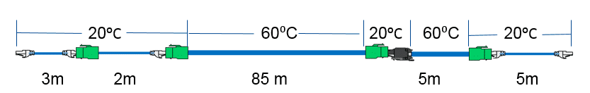
This model represents a full 100 m channel with 10 m of patch cords and an initial permanent link length of 90 m. I assumed that the connectors and patch cords were in a controlled environment (at room temperature, and insertion loss is always the same). Permanent links were assumed to be at a higher temperature of 60 degrees C (the same assumption used in ANSI/TIA TSB-184-A, where the ambient temperature is 45 degrees C and temperature rise due to PoE current and cable bundling is 15 degrees C).

Using the data from these tests, I was able to reach the full 100 m length with Belden’s 10GXS, a Category 6A cable. I then modeled Category 6 and Category 5e cables from Belden at that temperature, and wasn’t able to reach the full 100 m. Why? Because the insertion loss of the cable at this temperature exceeded the insertion loss performance requirement.

Read full article

Easy, Cost-Effective Way to Add Power with Industrial PoE Injectors

PoE Injectors can appease the growing power demands of energy-hungry devices in applications like physical security, transportation and automation – all in one device.

  • High-efficiency, low-waste power
  • Plug-and-play installation
  • Up to 240W of power from 8 ports

For recently developed or retrofit applications in need of maximum power without device limitations, these Power over Ethernet (PoE) injectors supply a high port count and up to 240 W of power.

PoE injectors join Hirschmann’s family of products built with industrial-grade housings and specific features to provide reliable power for industrial applications. They are the easiest and most cost-effective way to add high PoE power to both new and existing applications.

Benefits

  • Choose between active (integrated power supply) or passive (standalone module) devices for increased flexibility, depending on your needs.
  • Supports up to 240 W across 8 ports without load sharing, ensuring maximum power output. Each port can provide the maximum output power of 30 W.
  • Simple plug-and-play capability and compact size saves time and space while automatically detecting connected devices.

Features

  • Benefit from up to 8 available ports that deliver 30 W of power each
  • Enable PoE communication with a high number of devices using just one PoE Injector
  • Save costs with an all-in-one-solution and an efficient transfer of power (less wasted power) of >95 percent
  • Use in extreme environmental conditions, including wide temperature ranges (-45 °C to +85 °C for injector, -25 °C to +70 °C for injector plus power supply)
  • Install quickly and easily with automatic device detection and classification (IEEE 802.3at)
  • Meet important industry standards
    – Safety of Industrial Control Equipment: EN 60950-1, EN 61131-2, UL 60950
    – Transportation: EN 50121-4

Download Bulletin

Read full article

10 Factors to consider when Choosing a Rack PDU

In it’s simplicity, rack power distribution units (PDUs) are designed to provide electrical protection and distribute power to networking equipment within racks/cabinets. As the needs and requirements of data centers altar, so do options for rack PDU performance.

There are several questions to consider before selecting rack PDUs that will work well for your data center application. This list below will aid you in the right direction, ensuring that the PDUs you choose will fit the design of your data center today and in the future.

1. Type of Mount

Depending on where you want to station it, a rack PDU can be mounted horizontally or vertically. Installed horizontally inside the rack (taking up RU space) is one option; another option is to vertically mount a PDU on the back or side of the enclosure (not taking up any RU space). You will often see one vertically mounted PDU on the left side and one on the right side of a data center cabinet (although rack PDUs can be mounted on either side, based on preferences).

PDUs can be mounted so that power cords exit either at the bottom or top of the enclosure. (If your data center is on a slab, for example, the power cord needs to exit at the top of the enclosure because there is no raised floor for it to pass through.)

2. Amperage

Your power rating – the amount of sustained power draw a PDU can handle – determines the amperage level you’ll need. Why is this important? Because, for example, a PDU with a 30A fuse will blow if a 30A circuit experiences more than 30A of power for an extended period of time.

Per the National Electrical Code, 30A PDUs or higher are required to be equipped with a 20A breaker to prevent injury in the event of a short circuit.

3. Voltage

In addition to different amperages, there are different input voltage options for rack PDUs as well; 208/240V is the most common voltage output to computing gear, with a new trend moving toward 400V input. Confirm your infrastructure voltage, and you’ll know what type of voltage you need in your PDU.

4. Single- or 3-Phase Power

What type of input power do you have access to: single-phase power or 3-phase power? The type of power distribution in your data center will determine whether you need a single- or 3-phase PDU.

The difference involves where in the distribution system the phase is broken down. When it’s broken down at the distribution panel, power to the rack will be single-phase service (requiring single-phase rack PDUs). When all three phases are brought to each rack, then a 3-phase PDU is needed. In most data centers, the input power is 3-phase service.

Read full article

Which is Right for You: 40G vs 100G Ethernet?

Companies like as Google, Amazon, Microsoft and Facebook started their migration toward 100G in 2015 – and smaller enterprise data centers are now following suit. Plenty of these new 100G deployments adopt a singlemode fiber solution for longer reach that best suits their hyperscale data center architectures.

Comparing 40G vs. 100G optical transceivers currently available in the market, both have been developed and cost optimized for their designated reach and applications.

While weighing 40G vs. 100G Ethernet, and deciding which migration path makes more sense for your organization, here are some facts you should know:

  • Switches with 10G SFP+ ports, or 40G (4x 10G) QSFP+ ports, can support 10G server uplinks
  • Switches with 25G SFP28 ports, or 100G (4x 25G) QSFP28 ports, can support 25G server uplinks
  • 100G switches have already been massively deployed in cloud data centers; the cost difference between 40G vs. 100G is small
  • Most new 100G transceivers can easily support 40G operation
  • Some non-standard 100G singlemode transceivers are designed and optimized for cloud data center deployment; product availability for other environments is limited for the short term
  • Traditional Ethernet networking equipment giants Cisco and Arista have already started selling switch software on a standalone basis that goes into networking devices (such as a “white box” solution with merchant switch ASICs); this move accelerates hardware and software disaggregation and lowers overall ownership costs for end-users
  • According to Dell’Oro, 100G switch port shipments will surpass 40G switch port shipments in 2018.

When considering system upgrades from 10G, it’s essential to understand that 40G will also be needed to support the legacy installed base with 10G ports; 40G/100G switch port configurability will certainly accelerate 100G adoption in the enterprise market.

In 2017, 100G Ethernet is already ubiquitous – it will be mainstream, not just in hyperscale cloud data centers. Next-wave 200G/400G Ethernet will soon hit the market; standards bodies have already initiated a study group for 800G and 1.6T Ethernet to support bandwidth requirements beyond 2020.

Wrapping Up the Road to 800G

We’re almost finished with our blog series covering the road to 800G Ethernet. Subscribe to our blog to follow this series, as well as receive our other content each week. As part of this blog series, we’ve covered the following topics:


Read full article

Copyright © 2024 Jaycor International
Engineered by: NJIN Agency