A Genius Tool for Effective Facilities Management – PatchPro®

PatchPro® F – iPLM Infrastructure Physical Layer Management
Design, Build & Manage your Enterprise and Data Centre in Granular Detail

iPLM View

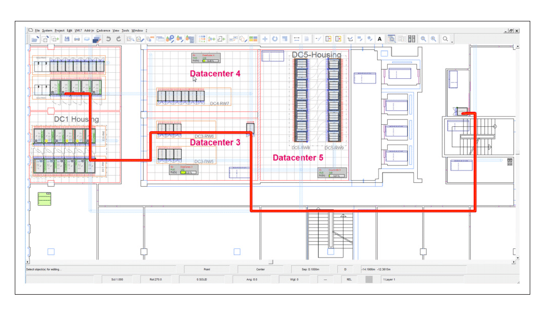
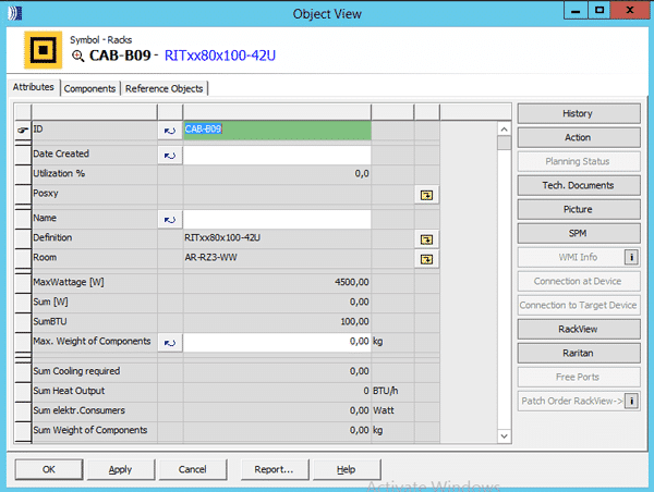
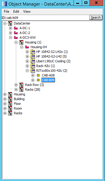
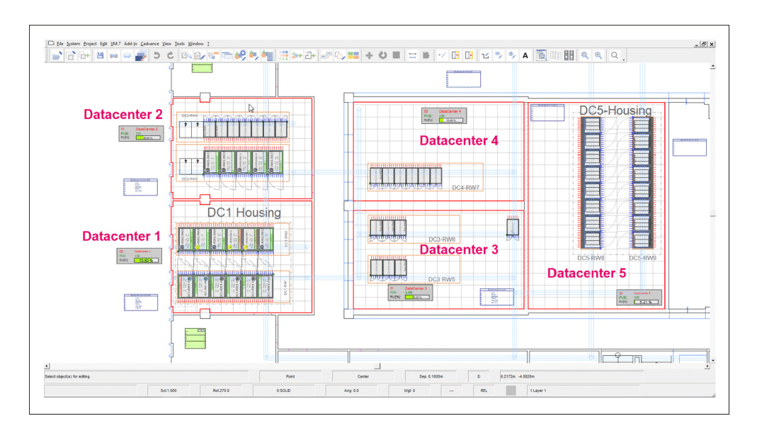
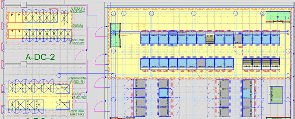
The iPLM View enables the user to access and visualize all objects, their attributes and cost centre’s within the entire facility:

  • All infrastructure (shown per floor)
    • Power distribution
      • DB Boards
      • Cabling, routes, and ducts
    • Ventilation ducts and CRAC Units
    • Cost Centre and PUE (real-time)
    • All other assets – offices/free space, PC’s, furniture

  • All network infrastructure and connectivity
    • Cabling, patch cords, wall-jacks, cable routes, and ducts
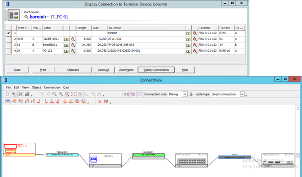
    • All connections from start-device through the network (point-to-point) to end-device

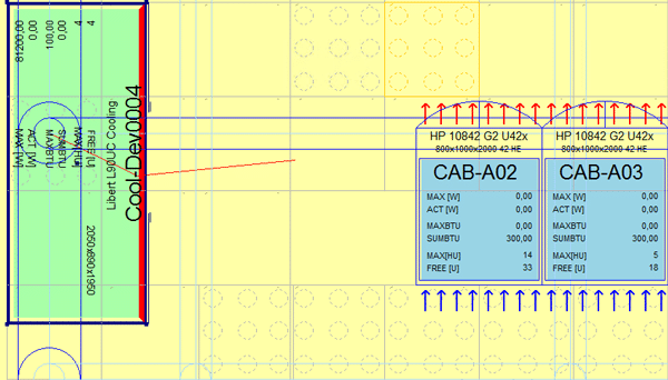
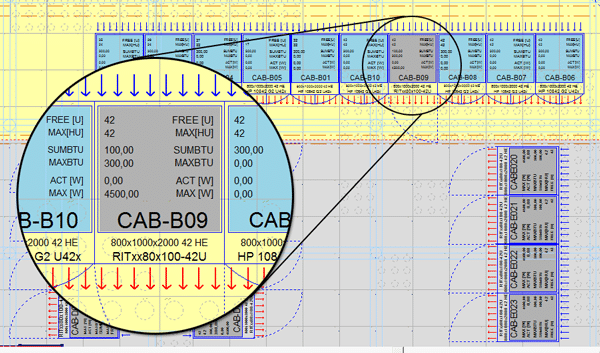
  • Cabinet/rack – real-time visualization of:
    • Dimensions (e.g. 800x1000x2000 42RU)
    • Free Rack Units
    • Sum of and Max BTU’s
    • Actual and Max Wattage
    • customize

  • Search (keywords) the object manager in granular detail for any criteria/objects within the entire facility
  • Quickly and easily navigate/zoom to the asset, view its connections and attributes

  • DC Managers create real-time design changes in planning mode and deploy work orders for execution.

IoT is Here to Stay: The Evolution of Converged Networks

Lately, I’ve been reminded of a quote that’s often attributed to Charles Darwin: “… It is not the most intellectual of the species that survives; it is not the strongest that survives, but the species that survives is the one that is able best to adapt and adjust to the changing environment in which it finds itself.”

The idea behind this quote remains true and applies well beyond the field of evolutionary biology.

Convergence (version 2.0) is here, and, to survive, we need to adjust, change and adapt to our changing environment. We cannot build networks for today (and for the future) like we have built them in the past, lest we go the way of the dodo bird.

Let’s look at the changes and improvements made since the first converged network (Convergence 1.0).

the-evolution-of-converged-networks-iot-is-here-to-stay-image-1

We established networks in the voice world that operated on high-availability systems we could count on without question. When you picked up the handset, you had a dial tone. With the rapid growth of data networks starting in the ’70s, it was inevitable that the industry would find synergies to allow voice and data telecommunications to exist on the same converged network.

the-evolution-of-converged-networks-iot-is-here-to-stay-image-2

In hindsight, I would argue that the technological and engineering issues were actually the easiest to overcome. The most difficult were the people issues: resistance to or fear of change, ego, protectionism, organizational boundaries, and risk avoidance, to name just a few. As the technologies grew, evolved and improved, so did our understanding. This helped us break down and overcome the people issues. A converged network bringing voice and data together is now the norm.

I’ve had a number of recent discussions with user groups in regard to the Internet of Things (IoT) and the opportunity that new technologies, applications and devices bring to an organization, as well as the challenges that can arise in adapting to this changing environment.

Traditionally, machine-to-machine (M2M) or device-based networks sat outside our converged networks, whether they be for digital building technologies, like video and security; smart cars; industrial networks; or many others.

the-evolution-of-converged-networks-iot-is-here-to-stay-image-3

In an IoT world, those networks still exist, as they always have. They may work on the same physical and/or logical networks with the same cables, boxes, and software, or they may use “like” networks to better interact.

The IoT world is here, and the level and rate of convergence are increasing in volume and velocity. IoT is a nebulous concept – hence all the cloud analogies. It will continue to morph as technologies evolve along with those that use it. Your corporate IoT cloud will look different from mine, and that’s okay.

the-evolution-of-converged-networks-iot-is-here-to-stay-image-4

Will we ever get to a true hyper-converged network where anything can talk to anything at any time? I don’t know – but that’s a people issue, not an engineering one. My lack of understanding or foresight doesn’t mean I don’t need to adjust and prepare for that eventuality. Converged networks will grow as they have; I will grow and adapt, or else I risk the potential of not being able to function in my changing environment.

Which brings me to adapting and adjusting to a changing environment from a network infrastructure frame of mind. Our TIA TR-42 (Telecommunications Cabling Systems ANSI/TIA-568 family), BICSI (TDMM and others) and proprietary or third documents must adapt and adjust. Whether they be specifications, standards or best-practice resources, they must evolve or face irrelevance (extinction, to extend the metaphor).

Our converged networks have evolved with higher speeds, higher power and more portability or mobility than ever before. More than any pundit, I remember prognosticating in the ’90s when people were amazed at shared megabit network capabilities and the ability to talk on the phone untethered. Simply creating faster networks, with higher grades of cabling, is not the answer.

Improvements in speed, noise immunity, power, portability, and mobility are all important, but they alone won’t get us where we need to go. We need to think differently, challenge the status quo and create new solutions. We need to adjust and adapt.

Traditional network guidance has usually centered on human telecommunications, whether directly, through things like voice and video, or indirectly through human-controlled devices, like our computers and tablets. Devices have been communicating through artificial means at least as long as we have, either through mechanical wires, pneumatics, hydraulics, electronic signals or other means. But now those machines are joining us in the digital world; rather than relying on proprietary protocols, they can now run on the same networks that our human-controlled devices do.

The bias toward human-controlled telecommunications is natural given the nature of standards development. Almost every standard defines “user” as a primary consideration when designing networks. Devices, despite having the ability to communicate on the same networks, have noticeably different requirements and, therefore, need different considerations. A one-size-fits-all approach to network design has arguably never worked well; it certainly won’t for our digital buildings and IoT environment of the future.

Using the smart building example, a “user” is a transient device on the network. The user goes home at the end of the day and on holidays, and user groups or customers change over with leases and occupancy changes. The lights, door controls, surveillance, security, mechanical and other digital building systems are effectively permanent fixtures. Our laptops, phones, and tablets are typically refreshed every few years. A building’s systems and technologies are expected to last much longer than that.

Furthermore, the operational risks, concerns, needs, and security requirements are different from “users” to “devices.” A person can get sick or take a vacation; a building cannot. The lights must always turn on, the HVAC systems must always work, the doors must always open, close and secure – without question. Even though a door control, lighting or HVAC system may not require the same bandwidth as a user, it does not mean that their network has lesser requirements. If anything, they may have higher requirements in some areas. If my laptop doesn’t function, I can still connect with my tablet or my phone. If a building doesn’t function, it impacts all the users – not just one.

I know that industry standards and best practices are adapting and adjusting to a new environment. Make sure your practices, specifications, assumptions, and procedures do as well. Otherwise, we risk new technology becoming an impediment to our goals – not through any fault of its own, but rather through how it was implemented. Make sure your team members, both external and internal, remember the lessons of Convergence 1.0 so they can be ready for 2.0, which is happening now. “We’ve always done it this way” might as well have been the mantra of the dodo bird.
Full article

Cost Effective Industrial Wifi

Now available in stock – JAYCOR offers a complete end-to-end solution for cost-effective industrial/outdoor ruggedized Wifi. Purchase all components for a turnkey solution:

  • Wireless AP (Access Point)
  • Omni or directional antennas
  • Antenna (N-Type) & Ethernet (RJ45) patch cords
  • Antenna & Ethernet lighting surge protection
  • Din Rail /Wall Mount PoE Switches, Media Converters and SFP modules
  • Din Rail Power Supplies & cabtyre
  • Outdoor enclosure


How PatchPro® Works

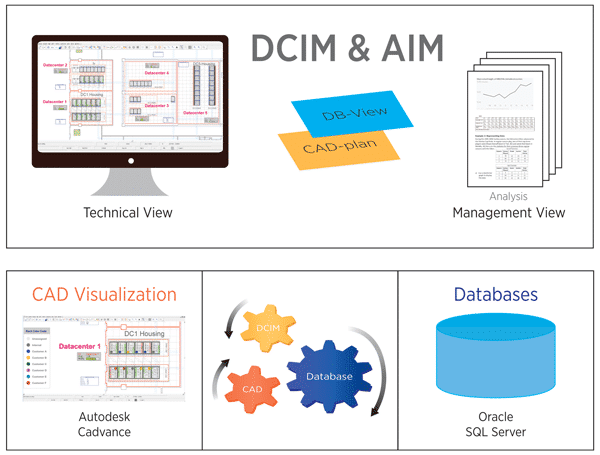
The key point is the Database

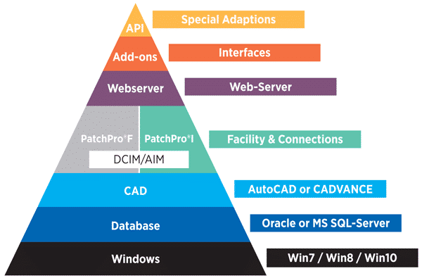
  • The Database sends all information / changes to the raphical user interface (GUI) through CADVANCE and or AutoCAD
  • The advantage of PatchPro is that you can manipulate the database by using the GUI which is quicker and easier
  • The Database and the GUI are connected. Objects changed on the system update in real-time

Key attributes of PatchPro® Software Solutions

Comprehensive technical functionality – both in the Facilities as well as in Data Centres.

  • Graphical User Interface’s (GUI) display:
  • Entire Facility & Multiple Site
  • Data Centre/s
  • Rack View/s
  • Open System (API) and database architecture

Network Cables; How Cable Temperature Impacts Cable Reach

There is nothing more disheartening than making a big investment in something that promises to deliver what you require – only to find out once it is too late that it is not performing according to expectations. What happened? Is the product not adequate? Or is it not being utilised correctly?

Cable Performance Expectations

This scenario holds true with category cable investments as well. A cable that can not fulfil its 100 m channel reach (even though it is marketed as a 100 m cable) can derail network projects, increase costs, cause unplanned downtime and call for lots of troubleshooting (especially if the problem is not obvious right away).

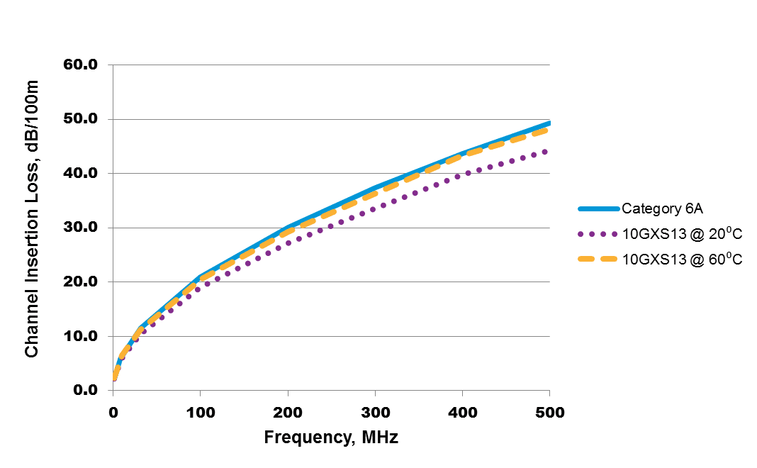
High cable temperatures are sometimes to blame for cables that don’t perform up to the promised 100 m. Cables are rated to transmit data over a certain distance up to a certain temperature. When the cable heats up beyond that point, resistance and insertion loss increase; as a result, the channel reach of the cable often needs to be de-rated in order to perform as needed to transmit data.

Many factors cause cable temperatures to rise:

  • Cables installed above operational network equipment
  • Power being transmitted through bundled cabling
  • Uncontrolled ambient temperatures
  • Using the wrong category cabling for the job
  • Routing of cables near sources of heat

In Power over Ethernet (PoE) cables – which are becoming increasingly popular to support digital buildings and IoT – as power levels increase, so does the current level running through the cable. The amount of heat generated within the cable increases as well. Bundling makes temperatures rise even more; the heat generated by the current passing through the inner cables can’t escape. As temperatures rise, so does cable insertion loss, as pictured below.

Testing the Impacts of Cable Temperature on Reach

To assess this theory, I created a model to test temperature characteristics of different cables. Each cable was placed in an environmental chamber to measure insertion loss with cable temperature change. Data was generated for each cable; changes in insertion loss were recorded as the temperature changed.

The information gathered from these tests was combined with connector and patch cord insertion loss levels in the model below to determine the maximum length that a typical channel could reach while maintaining compliance with channel insertion loss.

This model represents a full 100 m channel with 10 m of patch cords and an initial permanent link length of 90 m. I assumed that the connectors and patch cords were in a controlled environment (at room temperature, and insertion loss is always the same). Permanent links were assumed to be at a higher temperature of 60 degrees C (the same assumption used in ANSI/TIA TSB-184-A, where the ambient temperature is 45 degrees C and temperature rise due to PoE current and cable bundling is 15 degrees C).

Using the data from these tests, I was able to reach the full 100 m length with Belden’s 10GXS, a Category 6A cable. I then modeled Category 6 and Category 5e cables from Belden at that temperature, and wasn’t able to reach the full 100 m. Why? Because the insertion loss of the cable at this temperature exceeded the insertion loss performance requirement.

Read full article

Ethernet Switch Evolution: High Speed Interfaces

Technology development has always been driven by emerging applications: big data, Internet of Things, machine learning, public and private clouds, augmented reality, 800G Ethernet, etc.

Merchant Silicon switch ASIC chip development is an excellent example of that golden rule.


OIF’s Common Electrical Interface Development

The Optical Internetworking Forum (OIF) is the standards body – a nonprofit industry organization – that develops common electrical interfaces (CEIs) for next-generation technology to ensure component and system interoperability.

The organization develops and promotes implementation agreements (IAs), offering principal design and deployment guidance for a SerDes (serializer-deserializer), including:

  • CEI-6G (which specifies the transmitter, receiver and interconnect channel associated with 6+ Gbps interfaces)
  • CEI-11G (which specifies the transmitter, receiver and interconnect channel associated with 11+ Gbps interfaces)
  • CEI-28G (which specifies the transmitter, receiver and interconnect channel associated with 28+ Gbps interfaces)
  • CEI-56G (which specifies the transmitter, receiver and interconnect channel associated with 56+ Gbps interfaces)

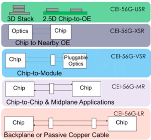
OIF’s CEI specifications are developed for different electrical interconnect reaches and applications to ensure system service and connectivity interoperability at the physical level:

  • USR: Ultra-short reach, for < 10 mm die to optical engine within a multi-chip module (MCM) package.
  • XSR: Extremely short reach, for < 50 mm chip to nearby optical engine (mid-board optics); or CPU to CPU/DSP arrays/memory stack with high-speed SerDes.
  • VSR: Very short reach, < 30 cm chip (e.g. switch chip) to module (edge pluggable cage, such as SFP+, QSFP+, QSFP-DD, OSFP, etc.).

Read full article

6 IoT Examples: The Internet of Things in Real Life

Even with all the talk about Internet of Things (IoT), it can be hard to come up with IoT examples that translate the concept to reality. Who is using it? Who is benefitting from it? How is it actually working for enterprises right now?

Without a doubt, IoT will bring more devices to your network – and cause an increase in data transmission requirements. According to HP, in 2010, there were 5 billion connected devices – just three years later, in 2013, the number nearly doubled to 9 billion. But what are those devices doing? What types of data are they gathering (and why)?

To help bring the concept of IoT to life, we rounded up some IoT examples that illustrate how this type of connectivity is already being used to improve efficiency and reduce expenses.


IoT Example No. 1: Philadelphia Streets Department

In Philadelphia, solar-powered, self-reporting trash compactors feature sensors that tell the compactor when the trash inside reaches a certain level. When that level is reached, the trash is automatically compacted. These sensors also send data back to the Philadelphia Streets Department to indicate how full they are, whether they need to be emptied, whether they need maintenance/repair, etc. Because employees now receive notifications about bins that are full or need attention, the team reduced collection frequency (and operating costs as a result), and are able to spend more time on other tasks instead.

Read full article

Achieving Solid Link Performance and Desired Link Distances with Singlemode Fiber

Having all new technologies and products available in the data center market, it is beneficial to plan in advance for potential amendments and upgrades. No matter which option you carry out, low-loss, high-bandwidth fiber cable used in conjunction with low-loss fiber connectors will always provide solid link performance and desired link distances with the number of connections you require.

As we’ve mentioned in earlier blogs, it is imperative to understand the power budget of new data center architecture, as well as the desired number of connections in each link. The power budget indicates the amount of loss that a link (from the transmitter to the receiver) can tolerate while maintaining an acceptable level of operation.

This blog equips you with singlemode fiber (SMF) link specifications so your fiber connections will have sufficient power and reach and desired link distances. Unlike multimode fiber (MMF), SMF has virtually unlimited modal bandwidth, especially operating at the zero-dispersion wavelength 1300 nm range, where material dispersion and waveguide dispersion cancel each other out.

Typically, a singlemode laser has a much finer spectral width; the actual reach limit isn’t bound by the differential modal dispersion (DMD) like it is in multimode fiber.

Read full article

The Right DC Supply Chain Can Improve Speed to Market

Trasfering capacity online faster, without sacrificing reliability or performance, is crucial for hyperscale and colocation data center projects, as providers and tenants continue to require additional equipment to support their growing infrastructure.

Recently reflecting on a panel discussion at last year’s CAPRE San Francisco Data Center Summit, which covered the top three things on the minds of data center industry executives today. In order of importance, their concerns were:

  1. Security
  2. Meantime to deploy
  3. Customer satisfaction

While all of these things are significant, No. 2 struck a chord. The ability to deploy data center capacity rapidly and efficiently can mean the difference between going live – or going broke! Meantime to deploy is not a concern that just popped up at a conference – rapid, on-time deployment has been a priority in the data center industry from Day One!

How can you reduce the amount of time it takes to “go live” for a tenant (or for your enterprise)? You could try to achieve better speed to market by working harder and faster, hiring more people and putting in longer hours. But there are only so many hours in the day – and only so much money in the budget.

Read full article

Time Sensitive Networking – 3 Benefits it Will Bring to Railway Communication

As demand for mass transit expands in densely populated urban areas, so do passenger demands for more entertainment, on-time delivery and safety. The Industrial Internet of Things (IIoT) and impending technologies like Time-Sensitive Networking (TSN) are making this feasible.

TSN is a novel technology, currently in development at the Institute of Electrical and Electronics Engineers (IEEE), that provides an entirely new level of determinism in standard IEEE 802.1 and IEEE 802.3 Ethernet networks. Standardizing Ethernet networks with TSN will deliver an important capability: deterministic, time-critical packet delivery.

It represents the next measure in the evolution of dependable and standardized automation technology and is certainly the next step in improving railway communication.

Time-Sensitive Networking Will Be Key for Railway Communication

Communication-based train control (CBTC), which uses wireless technologies to continually monitor and control the position of trains, could use TSN to guarantee real-time delivery of critical safety data on Ethernet networks also carrying non-safety related data. Ethernet networks standardized with TSN will support higher data bandwidths and reduce the number of devices required for railway communication. Ultimately, with more information being transmitted across railway Ethernet networks, TSN will ensure that the most critical data is prioritized to assure operations.

What does railway communication look like today, without TSN? The process is like a police car and a truck sharing a one-lane road: Imagine that a truck, (which represents non-time-critical information), is driving along a one-lane road and can’t see anybody behind or in front of him on the road. So, he drives the truck onto the next section of the road. But just as the truck enters this section, a police car (representing time-critical information) with emergency lights arrives and wants to overtake the truck to quickly reach an emergency situation further down the road. unfortunately, the truck has already turned onto the next section of the one-lane road and cannot move out of the way, causing an unexpected delay to the police car!

Read full article

Copyright © 2024 Jaycor International
Engineered by: NJIN Agency
This is a Blog Category Page